This guide explains how to evaluate and use the Extech EX900, a professional clamp-style electrical tester intended for current, voltage, resistance, and related troubleshooting tasks. It outlines the instrument’s role, operating principles, safety considerations, measurement workflow, maintenance needs, and selection criteria. Because specifications and included accessories may vary by market or production revision, users should confirm the current datasheet and manual before purchase or field work.
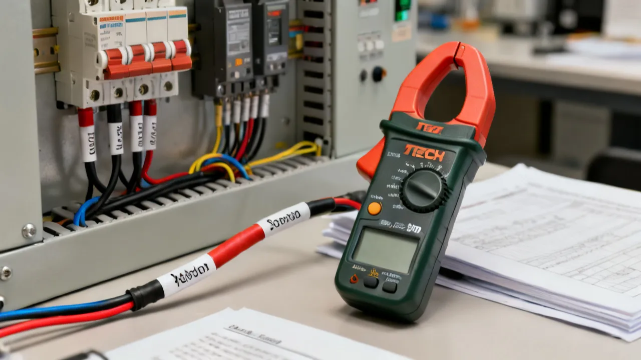
The Extech EX900 is generally identified as a professional clamp meter for electrical inspection and troubleshooting. Its principal advantage is the ability to measure current by placing the jaw around a conductor rather than disconnecting the circuit. That distinction matters in maintenance environments, where opening a live circuit can interrupt equipment operation, create an arc risk, or require a more complex isolation procedure.
For technicians, the instrument is best understood as a compact diagnostic platform rather than simply an ampere meter. A typical workflow may include checking AC or DC current, confirming voltage, testing continuity, examining resistance, and investigating irregular behavior in motors, control circuits, power supplies, battery systems, or building services equipment. The exact functions, ranges, accuracy, safety category, and accessories should always be verified in the documentation supplied with the particular Extech EX900 unit.
An industry specialist would normally assess this model in three stages. First, determine whether its measurement functions match the electrical systems being serviced. Second, confirm that its safety rating and operating limits are suitable for the installation. Third, evaluate whether the jaw shape, display, controls, and measurement response support the technician’s actual working conditions. A meter can be technically capable yet poorly matched to a cramped panel, a high-current feeder, or a field service routine.
The Extech EX900 may therefore appeal to electricians, maintenance engineers, HVAC professionals, facility teams, automation technicians, automotive specialists, and instructors who need a versatile instrument for routine electrical diagnosis. It should not, however, be treated as a substitute for proper isolation, lockout procedures, personal protective equipment, or formal electrical training.
Traditional current measurement with a handheld multimeter usually requires the meter to be connected in series with the circuit. That procedure can be appropriate in controlled low-energy applications, but it is not normally the first choice for checking a running motor, distribution feeder, or installed load. A clamp meter instead senses the magnetic field surrounding a conductor. The technician opens the jaw, encloses the conductor, and reads the resulting current value.
This method improves efficiency because it reduces circuit disturbance. It is particularly useful when comparing phases, checking starting behavior, investigating unbalanced loads, or confirming whether a machine is drawing current under operating conditions. It also helps maintenance teams perform preliminary assessments without removing conductors from terminals or interrupting production.
There is an important limitation: the jaw must surround only the conductor being measured. If both the outgoing and returning conductors pass through the jaw, their magnetic fields may cancel, producing a result close to zero even when the circuit is energized. This is one of the most common causes of incorrect clamp-meter readings.
Clamp measurement also depends on conductor position. A conductor placed near the center of the jaw generally provides the most consistent result. Crowded cable bundles, adjacent magnetic fields, and conductors running at unusual angles can influence readings. The technician should keep the jaw fully closed and avoid using it as a mechanical tool for moving, separating, or gripping cables.
Another practical consideration is access. The clamp must be able to open far enough to fit around the conductor, and the surrounding installation must leave enough space for the meter body and the operator’s hand. A technically suitable meter may be difficult to use safely if the panel is densely packed or the conductor cannot be isolated from neighboring wires. In those circumstances, the measurement plan may need to include temporary access arrangements, de-energization, or a different instrument.
When reviewing the Extech EX900, prospective users should begin with the functions needed for their work rather than focusing only on the product name. A professional clamp meter commonly combines several electrical measurements, but not every function is equally important in every environment.
AC current measurement is central to diagnosing motors, heaters, pumps, air-conditioning equipment, lighting circuits, and distribution systems. The reading can help identify an overloaded branch, a failed component, a phase imbalance, or a load that is not operating as expected.
When measuring AC current, the user should identify the conductor, select the appropriate current mode, open the jaw, and place the jaw around one conductor only. The measurement should be allowed to stabilize before it is interpreted. Loads with rapidly changing demand may produce a fluctuating display, so the technician should observe the reading over a suitable period rather than recording a single unstable value.
It is also useful to record the equipment’s operating state. A pump may draw different current when its discharge valve is open or closed. A compressor can change its current as pressure and temperature vary. A heater may cycle through thermostatic control. Without that context, a current value may appear abnormal when it is actually normal for a particular stage of operation.
DC current capability is useful in battery systems, control panels, photovoltaic-related service work, automotive applications, charging equipment, and industrial electronics. DC clamp measurement is more sensitive to zero offset and residual magnetism than many users expect. Before measuring, the instrument may need to be zeroed according to the manufacturer’s procedure.
If a DC reading appears unexpectedly high or does not return to zero, the user should remove the meter from the conductor, close the jaw, and perform the recommended zero adjustment. The jaw should also be fully closed. Mechanical stress, nearby magnetic fields, and previous high-current measurements may affect the baseline.
DC current also has direction. Depending on the instrument’s design, the display may show a negative sign when current flows opposite to the meter’s reference arrow or expected orientation. A negative indication is not automatically a fault. It may simply mean that the conductor should be repositioned or that the direction should be documented as part of the test result.
Voltage testing confirms the electrical potential between two points. It is often performed before current measurement to establish whether a circuit is energized and to check whether the supply is within the expected range. Voltage measurement requires test leads, so the technician must observe correct lead placement and terminal selection.
A key safety principle is that voltage measurement is performed across a circuit, while current measurement using test leads is performed in series. Confusing these two procedures can cause a short circuit and damage the instrument or installation. A clamp meter’s current jaw does not remove the need to use the proper input terminals for voltage testing.
Begin with a higher voltage range when the voltage is unknown, unless the instrument’s approved autoranging procedure is being used. Never assume that a familiar-looking conductor is safe to touch. Confirm the circuit identification, keep fingers behind the probe guards, and avoid allowing the probe tips to bridge adjacent terminals.
Resistance measurement is normally performed on a de-energized circuit. It can help assess heating elements, fuses, windings, cables, switches, and passive components. Continuity mode provides a quicker indication of a low-resistance path and is practical when tracing wiring or checking whether a switch closes correctly.
Resistance readings can be misleading when other components remain connected in parallel. A circuit may show a lower resistance than the individual component because current has multiple paths. For reliable diagnosis, isolate the component where necessary and follow the circuit diagram.
Long test leads and poor probe contact can also influence low-resistance measurements. When checking a cable, the technician should make firm contact with clean conductive surfaces and account for the resistance of the leads if the measurement requires precision. Continuity beeper thresholds are intended for quick checks and should not be confused with a detailed resistance assessment.
Some configurations of professional clamp meters include additional functions such as diode testing or capacitance measurement. These features can be useful for electronic troubleshooting, but they should not be assumed without confirming the exact EX900 documentation. Capacitors must be discharged appropriately before testing, and semiconductor measurements should be performed with the circuit isolated.
A capacitance reading can be affected by components connected in parallel, leakage paths, residual charge, or a circuit board that has not been disconnected from other sections. The displayed value should therefore be compared with the component’s marked value and the equipment service information. A diode test can indicate forward voltage behavior, but it is not a complete evaluation of a power semiconductor under operating load.
Depending on the model revision and market specification, an instrument in this category may offer frequency, temperature, inrush, peak, or related modes. These capabilities can expand the diagnostic value of the meter, especially in variable-speed drives, motors, and HVAC systems. However, specialized modes require careful interpretation. A frequency value, for example, does not by itself confirm that a drive output is suitable for a motor. Likewise, an inrush reading depends on the capture window, load behavior, and instrument response.
Temperature accessories also require attention to polarity, range, insulation, and physical placement. A temperature probe placed near a heat source may not represent the actual winding, bearing, terminal, or ambient temperature of interest. The user should follow the accessory instructions and avoid placing a probe where it could become entangled in moving machinery or contact energized parts.
Accuracy is often presented as a headline specification, but the number should be interpreted with its conditions. Meter accuracy may be expressed as a percentage of the reading plus a number of counts. The result can vary according to measurement range, frequency, temperature, waveform, battery condition, and the duration of the measurement.
For a technician, resolution is also important. A high-current range may be suitable for feeders but may not display small standby currents with enough detail. Conversely, a sensitive low-current range may provide useful information on control circuits while being unsuitable for a large industrial load. The most appropriate instrument is the one that offers a useful combination of range, resolution, stability, and safety for the intended application.
True-RMS capability, when included and verified for the specific unit, can improve measurements of non-sinusoidal AC waveforms compared with average-responding instruments. Modern loads such as switching power supplies, electronic lighting, variable-frequency drives, and computer equipment can draw current in distorted waveforms. Even with a True-RMS meter, users should check the specified crest-factor and frequency limitations. A label alone does not guarantee accurate performance under every waveform condition.
Experts also distinguish between instrument accuracy and system accuracy. A meter may be operating within its published specification while the overall result remains uncertain because of conductor placement, electrical noise, unstable load behavior, contact quality, or an unsuitable range. Good measurement practice controls these variables before the number is accepted.
Environmental conditions can matter as well. Extreme cold or heat may shift the meter’s response, while moisture and contamination can compromise insulation and control operation. If measurements are being compared over time, it is useful to record whether the instrument was operating in a similar environment and whether the battery was adequately charged.
Electrical measurement carries an inherent risk. Before using the Extech EX900, the user should read the current manual, inspect the housing and leads, verify the measurement category, and confirm that the installation does not exceed the instrument’s voltage and current limits. The correct safety category depends on where the measurement is made, such as a receptacle circuit, a fixed distribution panel, or equipment connected to a service entrance.
The meter’s category marking is not a general permission to work on any circuit. It describes the type of transient environment for which the instrument has been assessed when used within its stated limits. Users must also consider available fault current, arc-flash risk, enclosure conditions, moisture, temperature, and the required protective equipment.
The most important practical point is that a clamp meter does not make energized work automatically safe. It reduces the need to open a circuit for current measurement, but it does not eliminate the hazard of contact with live conductors or an unexpected fault. If the enclosure is damaged, conductors are exposed, or the task cannot be completed without excessive reach or awkward positioning, the technician should stop and use an approved alternative procedure.
The following procedure provides a general framework. The manufacturer’s instructions and the site’s electrical safety rules take priority if they differ.
Voltage testing is often treated as routine, yet it is one of the situations in which incorrect lead placement can create an immediate hazard. Before connecting the probes, confirm which terminals are intended for voltage measurement. The black lead is normally connected to the common terminal and the red lead to the voltage terminal, but the markings on the actual instrument should be followed.
Begin on a higher range when the voltage is unknown and move to a more suitable range only when the conditions are understood. Place the probes across the intended points without allowing the metal tips to bridge adjacent terminals. In a panel, a probe slip can create a phase-to-phase or phase-to-ground fault.
When checking a supposedly de-energized circuit, use an approved live-dead-live method or the procedure specified by the responsible electrical authority. The instrument should be tested on a known energized source, used on the target circuit, and tested again on the known source. This confirms that the meter remained functional during the test.
Voltage readings should also be evaluated under load where appropriate. An open-circuit supply may appear normal, while a poor connection or undersized conductor causes voltage drop when the equipment operates. A useful diagnosis may require comparing supply voltage at the source and at the load during the same operating condition.
When comparing phase-to-phase or phase-to-neutral voltages, use a consistent sequence and document the reference points. A voltage imbalance can damage motors and other equipment, but an apparent imbalance can also result from a floating neutral, an incorrect reference, a loose probe, or a control circuit that is not arranged as assumed.
Motors and HVAC equipment create demanding measurement conditions because their current may change rapidly during starting, acceleration, loading, cycling, or defrost operation. The Extech EX900 can support a structured diagnostic process, provided the user understands what each reading represents.
For a motor, begin with the nameplate information and the manufacturer’s service requirements. Measure the relevant phase currents under a defined operating state. Compare the readings with one another and with the expected load. An imbalance may originate from supply conditions, loose connections, winding problems, mechanical loading, or instrumentation error. Current alone cannot identify the root cause.
Starting current and inrush behavior deserve special attention. The peak observed by a handheld instrument depends on the motor, supply impedance, switching method, measurement location, and capture response of the meter. A low value does not necessarily prove that the motor has no starting surge, and a brief high value does not automatically indicate failure. Measurements should be repeated and correlated with symptoms such as nuisance trips, slow acceleration, overheating, or abnormal sound.
In HVAC service, current measurement may help assess compressors, blower motors, condenser fans, and electric heaters. The technician should account for the operating mode, ambient conditions, refrigerant-related service state, and control sequence. A compressor’s current can vary with pressure and temperature, so a reading should be interpreted alongside the equipment manufacturer’s service data.
In variable-speed systems, the waveform and frequency may differ from ordinary utility power. The user should verify that the meter’s stated capabilities cover the output being measured. If the instrument is not designed for a particular drive output, the reading may be misleading or the measurement may expose the user and equipment to unnecessary risk.
Current should also be compared with voltage and mechanical symptoms. A motor drawing high current at normal voltage may be overloaded mechanically, while high current accompanied by low voltage may point toward supply or conductor problems. A motor drawing very little current may have an open winding, a failed contactor, a disconnected load, or a control fault. A coordinated set of measurements is more informative than any single reading.
DC clamp measurement can be valuable when diagnosing charging systems, battery banks, control circuits, and auxiliary loads. It allows a technician to observe current without disconnecting a cable, which is useful when a system must remain operational during diagnosis.
When checking a battery-related system, first establish whether the current is charging, discharging, or pulsed. Direction matters in DC measurement, and the meter’s polarity indication should be understood before the reading is documented. A negative sign may indicate that the conductor’s current direction is opposite to the meter’s reference orientation, not that the system is malfunctioning.
Small parasitic currents can be difficult to measure accurately with a large-current clamp meter if the instrument’s resolution or sensitivity is not appropriate. The technician should confirm the low-current performance of the specific EX900 configuration and consider a dedicated instrument when the expected current is very small.
High-current battery systems also present arc and short-circuit hazards. A clamp measurement may avoid disconnecting the cable, but the jaw and meter must still be kept away from terminals, tools, and conductive jewelry. The battery chemistry, available fault current, and installation design should be considered in the risk assessment.
In automotive work, electronic control units may enter sleep or wake cycles, causing a changing current pattern. A single instantaneous reading may not reveal the fault. The technician may need to observe the vehicle or system over time, record the normal shutdown sequence, and compare the result with manufacturer specifications.
| Observed issue | Likely cause | Recommended check |
|---|---|---|
| Current reads near zero | The jaw surrounds both outgoing and returning conductors, or the wrong function is selected. | Clamp around one conductor only and confirm AC or DC mode. |
| DC current does not return to zero | Residual magnetism, nearby magnetic influence, or the absence of zero adjustment. | Remove the conductor, close the jaw, and follow the specified zero procedure. |
| Reading is unstable | Variable load, electrical noise, poor jaw closure, or an unsuitable measurement range. | Improve positioning, close the jaw fully, observe the load cycle, and verify the range. |
| Resistance appears unusually low | The component remains connected in parallel with other circuit paths. | De-energize and isolate the component before repeating the test. |
| Voltage appears absent | Incorrect terminal selection, blown input protection, poor probe contact, or a genuinely dead circuit. | Verify the meter on a known source and inspect the leads and connections. |
| Display shows overload | The selected range or function is unsuitable for the measured value. | Stop, reassess the expected measurement, and select a compliant range. |
| Different phases show different values | Load imbalance, supply conditions, conductor position, or changing operating state. | Repeat under comparable conditions and investigate the complete system. |
| Reading changes when the jaw moves | External magnetic fields, nearby conductors, or an incompletely closed jaw. | Center the conductor, close the jaw, and repeat away from adjacent magnetic sources where possible. |
| Continuity test gives an unexpected result | Parallel circuit paths, a charged capacitor, oxidized contacts, or a faulty fuse. | Isolate the circuit, discharge stored energy, and test the component independently. |
The appropriate comparison is not simply between brands. It is between measurement needs. A clamp meter may be the best primary tool for current checks, while a bench multimeter, insulation tester, power-quality analyzer, or specialized automotive meter may be more suitable for other tasks.
| Instrument type | Primary strength | Typical limitation | Where the EX900 may fit |
|---|---|---|---|
| Standard handheld multimeter | Detailed voltage, resistance, continuity, and low-current measurements using test leads. | Current measurement may require series connection and circuit interruption. | The EX900 adds non-contact conductor current measurement for many routine inspections. |
| Clamp meter | Fast current measurement on installed conductors. | Jaw access, conductor placement, and low-current resolution can limit results. | The EX900 belongs in this category and should be judged by its verified ranges and safety marking. |
| Insulation resistance tester | Tests insulation condition using a controlled test voltage. | Not a general replacement for a clamp meter or ordinary multimeter. | Use alongside the EX900 when insulation diagnosis is required and the circuit is isolated. |
| Power-quality analyzer | Records waveform, harmonics, events, and longer-term electrical behavior. | More complex and less convenient for quick single-point checks. | The EX900 may provide preliminary readings before advanced analysis. |
| Bench precision multimeter | Stable, high-resolution measurements in a controlled laboratory environment. | Less portable and generally unsuitable for clamping around large installed conductors. | The EX900 is more practical for field work and distribution equipment. |
This comparison illustrates why a buyer should define the job before selecting the instrument. If the work centers on installed conductors and operational equipment, the clamp format is a meaningful advantage. If the work requires highly precise low-level measurements, insulation testing, waveform recording, or laboratory repeatability, an additional instrument may be necessary.
Availability and configuration can change by region. Retail listings may use different descriptions, package contents, warranty terms, or product-status labels. Buyers should confirm the model number carefully and compare the seller’s information with the current manufacturer documentation.
Price should be assessed in relation to these factors. The lowest listed price may not represent the lowest total cost if it excludes essential accessories, has unclear warranty coverage, or comes from a source that cannot confirm product authenticity. Conversely, paying for functions that will never be used may not be efficient. A practical procurement decision weighs capability, safety, serviceability, and expected frequency of use.
Buyers should also consider ergonomics. A meter used several times each day must be comfortable to hold, simple to operate, and readable in the lighting conditions of the workplace. A backlit display can be helpful inside a cabinet, while a large jaw opening may be more important for distribution work. Control placement matters because the technician may need to change a function while wearing gloves or standing in an awkward position.
The most reliable source for technical claims about the Extech EX900 is the current manufacturer datasheet and user manual for the exact model. These documents should be used to verify electrical limits, accuracy, operating conditions, measurement categories, battery type, environmental restrictions, and maintenance instructions. A distributor’s listing can assist with availability, but it should not replace the manufacturer’s documentation when safety or technical suitability is being evaluated.
For workplace procedures, users should also consult applicable electrical safety regulations, employer risk assessments, equipment service manuals, and recognized standards adopted in their jurisdiction. In the United States, organizations may refer to OSHA requirements and NFPA 70E practices where applicable. Other countries may apply different regulations and terminology. The relevant authority’s current rules should be followed rather than relying on a generic online summary.
Calibration requirements should be based on the quality system and risk level of the organization. A facility that records measurements for compliance, commissioning, or critical maintenance may require documented calibration at defined intervals. A meter used for informal preliminary checks may follow a different policy. The interval should be determined by use, environment, history, and organizational requirements—not by an arbitrary assumption.
Documentation should remain accessible to everyone who may use the instrument. A shared maintenance department can reduce errors by keeping the manual with the meter, labeling the instrument with its calibration status, and recording any damage or repair. These simple controls help prevent a worker from unknowingly using a meter that is overdue for calibration or unsuitable for a particular measurement.
Routine care extends the instrument’s useful service life and reduces the chance of misleading results. After use, wipe the exterior with a material approved by the manufacturer. Do not immerse the meter or apply solvents unless the documentation expressly permits them. Keep the jaw faces clean and free from material that could prevent full closure.
Store the Extech EX900 in a dry environment away from excessive heat, direct sunlight, corrosive chemicals, and strong magnetic fields. If the instrument will not be used for an extended period, follow the battery-storage guidance in the manual. A leaking battery can damage internal contacts and the enclosure.
Test leads deserve particular attention. Their insulation can deteriorate from bending, heat, oil, or sharp edges. The probe tips should remain secure, and the protective finger guards should not be removed. Replace damaged leads rather than attempting an improvised repair.
Calibration is not the same as a quick functional check. A functional check may show that the display responds and that the meter produces a plausible reading. Calibration compares the instrument with a traceable reference under defined conditions. If the EX900 is used for safety-critical or quality-controlled measurements, calibration should be performed by a competent laboratory or service provider according to the organization’s requirements.
Before beginning a shift, some maintenance teams perform a short verification sequence: inspect the case, check the leads, confirm the battery indication, test the meter on a known source, and verify that the jaw opens and closes smoothly. This does not replace calibration, but it can detect obvious problems before the meter is taken to a live installation.
A skilled technician rarely treats one number as a complete diagnosis. Instead, the number is compared with a reference: a rating plate, circuit diagram, previous maintenance record, parallel phase, expected operating sequence, or manufacturer’s service value.
For example, a motor current reading may be acceptable at light load but abnormal at full load. A voltage reading may be normal with no load yet fall when a heater or compressor starts. A resistance value may be correct at room temperature but change significantly as a component warms. The measurement must be linked to operating conditions.
Repeatability is another important consideration. If the same measurement changes substantially when the jaw is moved slightly, inspect the conductor arrangement and external magnetic influence. If the value changes with the position of a test probe, examine contact quality and possible oxidation. If the display changes in a predictable cycle, identify the equipment’s control sequence before concluding that the meter is inaccurate.
Experts also distinguish between a symptom and a cause. A high current may result from mechanical overload, low voltage, incorrect configuration, bearing friction, or a winding issue. A low current may indicate an open circuit, a failed load, a control problem, or simply that the equipment is in standby. The Extech EX900 can provide evidence, but the technician must combine it with system knowledge.
Good records make future comparisons much easier. A useful maintenance entry can include the asset identification, conductor or phase measured, voltage, current, equipment state, ambient conditions, meter range, and any relevant alarm or symptom. Over time, trends may reveal deterioration that would not be apparent from one isolated inspection.
Before field use, the following conditions should be satisfied:
If any of these conditions cannot be met, the correct action is to stop and reassess the task. A capable meter cannot compensate for an unsuitable work method. In some cases, the safest and most reliable choice is to de-energize the system and use a different diagnostic process rather than attempting a difficult live measurement.
The Extech EX900 is generally presented as a clamp-style electrical meter that combines current measurement through its jaw with additional test-lead functions. The precise functions and ranges should be confirmed in the documentation for the exact unit being considered.
Its clamp design is intended to measure current around a conductor without placing the meter in series. The jaw must surround one conductor only, and the user must follow the instrument’s current limits and safety instructions.
The jaw may be surrounding both the outgoing and returning conductors, causing magnetic cancellation. Other possibilities include selecting the wrong AC or DC mode, failing to close the jaw fully, measuring below the instrument’s useful resolution, or encountering a fault in the meter.
No. A general clamp meter and an insulation resistance tester perform different tasks. Insulation testing requires a controlled test voltage and specific procedures. Use the appropriate instrument for the diagnostic objective.
Resistance, continuity, diode, and similar functions should not be used on an energized circuit. De-energize, isolate, and verify the circuit according to the applicable safety procedure before connecting the meter for these tests.
It can be important when measuring distorted or nonsinusoidal AC waveforms produced by electronic equipment, switching supplies, or drives. The user should still review the meter’s frequency and waveform limitations because True-RMS performance is not unlimited.
Use the correct DC function and follow the manufacturer’s zeroing procedure. Position the conductor consistently, close the jaw completely, and check the direction indication. Nearby magnetic fields and residual magnetism can influence the baseline.
Confirm the exact model, functions, ranges, accuracy, safety category, jaw opening, accessories, warranty, calibration requirements, and seller documentation. Product listings can vary, so the current manufacturer datasheet and manual should be treated as the primary technical references.
There is no universal interval suitable for every user. Follow the organization’s quality policy and consider frequency of use, measurement criticality, environmental exposure, previous calibration results, and applicable regulations. A qualified calibration provider should perform formal calibration when required.
It may be suitable for certain industrial-panel measurements if its verified safety category, voltage rating, jaw capacity, and measurement limits match the installation. Panel work also requires appropriate training, protective equipment, and an approved energized-work or isolation procedure.
Only if the cable arrangement and measurement principle support that method. If a cable contains both the outgoing and returning paths of the same circuit, the magnetic fields may cancel. For dependable results, clamp around one individual current-carrying conductor unless the manufacturer specifically describes another arrangement.
Nameplate current is normally associated with a defined operating condition, often a particular voltage, frequency, load, and temperature. Actual current may be lower during light loading or higher during starting and overload. Check the operating state, supply voltage, measurement method, and manufacturer’s expected values before deciding that the difference indicates a fault.
The Extech EX900 is useful when viewed as a field-oriented diagnostic instrument that combines clamp-current convenience with the broader functions expected from a professional handheld meter. Its value lies in reducing circuit interruption during current checks, supporting structured troubleshooting, and helping technicians compare real operating conditions with equipment requirements.
Its effectiveness depends on correct application. The user must select the right function, enclose only the intended conductor, account for waveform and load behavior, maintain the instrument, and interpret readings in context. Safety category, operating limits, calibration status, and current documentation are more important than a broad product description or an isolated price claim.
For buyers, the final decision should be based on verified specifications and the actual work environment. For technicians, the best results come from a disciplined sequence: identify the circuit, assess the hazard, confirm the instrument, measure consistently, document conditions, and investigate the system rather than relying on a single displayed value. Used within those boundaries, the Extech EX900 can serve as a practical component of an electrical maintenance and troubleshooting toolkit.
Striking the Perfect Balance: Navigating Premiums and Out-of-Pocket Expenses in Senior Insurance Plans

Explore the Tranquil Bliss of Idyllic Rural Retreats

How to Make Lasting Memories at Disneyland Attractions

Affordable Phones and Plans for Seniors

Affordable Full Mouth Dental Implants Near You

Unlock the Top Kept Secrets to Finding Your Ideal Dentist for Flawless Dental Implant Results!

Discovering Springdale Estates

Unveiling RS Sul Telecom Services

The Guide to Car Trading


Understanding Proportional Valves
Proportional valves are hydraulic components vital for controlling fluid flow and pressure with high precision in various industrial applications. Their importance in automation and manufacturing settings stems from their ability to offer variable output in response to input signals, greatly enhancing system efficiency and performance.
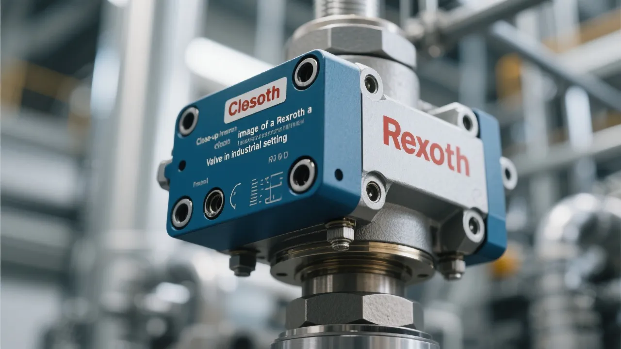
Understanding Rexroth Valve Systems
Rexroth Valves are quintessential components in various industrial applications, known for their precision and reliability. These hydraulic, pneumatic, and electrohydraulic valves regulate fluid flow in machinery, ensuring optimal performance and safety. Understanding their functionality and benefits is crucial for industries seeking efficiency and sustainability in their operations.

Unveiling Thermo Fisher Chromatography
This article explores the pivotal role of Thermo Fisher Chromatography in modern analytical science. Chromatography is crucial for separating compounds within mixtures, making it indispensable in industries such as pharmaceuticals and environmental testing. Thermo Fisher Scientific stands out in this field for its innovative solutions, leading to improved accuracy and efficiency in research and development.

Understanding Corrosion Inhibitor Manufacturers
In today's industrial landscape, corrosion inhibitor manufacturers play a crucial role in safeguarding equipment and infrastructure against corrosive damage. These manufacturers provide specialized chemicals that prevent corrosion in various environments, including industries such as oil and gas, marine, and construction. Understanding their operations and offerings is essential for selecting the right supplier and maintaining asset longevity.
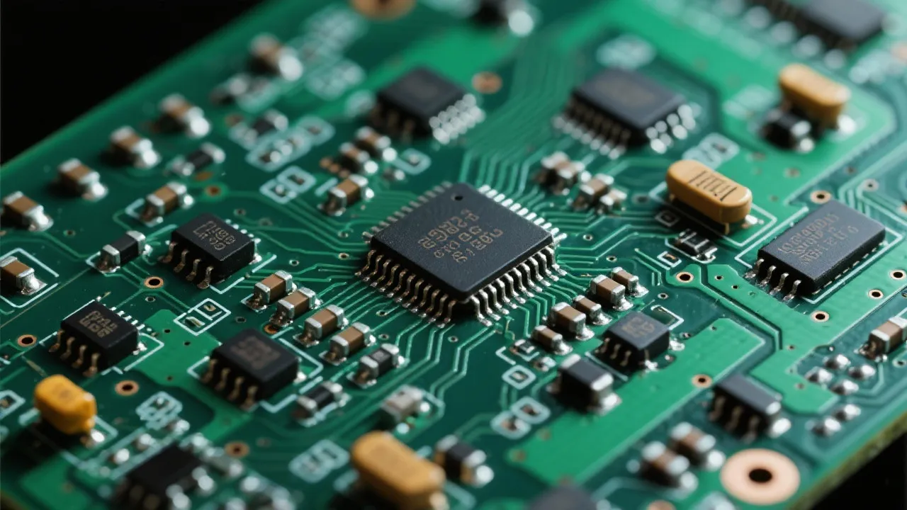
Analyzing Lm66100 Digikey Components
This article offers an in-depth analysis of the Lm66100 component available through Digikey, a renowned distributor of electronic components. The Lm66100, a load switch, is integral in industry applications, providing efficient power management. This piece explores its features, applications, and availability through Digikey, while offering a comprehensive guide for industry professionals seeking to optimize their electronic designs.

Leading Corrosion Inhibitor Suppliers
Corrosion inhibitor manufacturers play a crucial role in protecting materials from degradation. These companies specialize in creating chemical compounds that slow down or prevent the corrosive effects on various surfaces, especially metals. Understanding their production processes and solutions offered is vital for industries reliant on metal infrastructure.